
The task for this week entailed using the provided engineering drawing to create a Computer Aided Design (CAD) model for the phone case base. The drawing below presents the details of the three-dimensional part in a two-dimensional format.
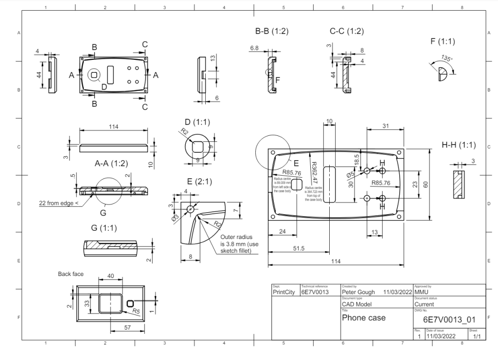
Engineering drawings allow for the communication of precise design specifications, dimensions, and tolerances between stakeholders. They provide a visual representation of the design, aiding in decision-making, problem-solving, and quality control. Engineering drawings also serve as official documentation of the design, capturing essential details and specifications required for manufacturing and regulatory compliance.
Some details were clarified in the following additional diagrams:
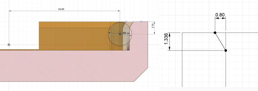
These images highlighted the critical dimensions of the snap-fit indentations and the chamfer around the top of the case, both of which had been omitted from the main drawing.
The CAD model could have been created in a numerous different software packages (such as Solidworks, Inventor, or Siemens NX), but Fusion was chosen due to it’s accessibility, compatibility with a variety of file formats, and its low cost. Additionally, since it is cloud based, it is easy to use it from multiple locations and multiple computers.
To create this model the Design workspace and specifically the solid environment was used. Here a parametric and history based design was created, that allowed for easy modification of dimensions and features if necessary. Below is a video showing the steps taken to create the CAD model.
Next week the production method will be chosen.
