This week the CAD model of the phone case base will be used to produce a physical prototype.
Before a 3D model can be printed it needs to be translated into commands that the printer can understand, the language most commonly used is G-code. This programming language consists of a series of alphanumeric codes that instruct the machine on how to move, position, and operate its tools to create a physical object based on a digital design. G-code commands control parameters such as toolpath, speed, feed rate, and tool changes, enabling precise control over the manufacturing process.
In order to produce G-code from a 3D model, slicing software is used. There a variety of different applications available, including: Cura, Simplify3D, and Slic3r. They are compatible with a wide range of printers and all have their own benefits and drawbacks; however, since Prusa i3 MK3S machines will be used PrusaSlicer has been chosen. This is a fork of Slic3r that is developed by Prusa Research and optimised for use with their printers.
To import the model into PrusaSlicer it must first be exported from Fusion in the form of a mesh file. There are a variety of formats that could be used such as STS, 3MF, or OBJ. All would be suitable for this project, but 3MF has several advantages over the others including:
- Improved geometry representation with higher-order surfaces
- Better color and texture support directly within the file
- Enhanced compression for smaller file sizes
- Native support for lattice structures
- Improved interoperability between software and hardware platforms
- Units can be specified directly within the file, ensuring consistency in measurement across different software and hardware platforms
After export from Fusion, the 3MF file was imported into PrusaSlicer and then the settings were systematically worked through.

Nozzle Size
Typically Prusa i3 MK3S printers use 0.4 mm nozzles as these afford a good compromise between printing speed and detail level. However, since the phone cases need to be produced in large quantities, it was decided to first test printing the case with a 0.6 mm nozzle. If the detail is sufficient, the larger nozzle will be a better choice due to the following advantages:
- Faster Printing: A larger nozzle diameter allows for faster extrusion rates, resulting in quicker print times compared to smaller nozzles
- Increased Strength: Larger extrusion width will cause printed parts have stronger inter-layer adhesion, enhancing overall structural integrity
- Reduced Clogging: A wider nozzle diameter is less prone to clogging, as it allows for smoother extrusion of filament, particularly with materials prone to jamming
- Better Layer Adhesion: The wider extrusion width facilitates better bonding between layers, reducing the risk of delamination and improving part durability
Filament Material
Recycled polylactic acid (rPLA) was chosen as the filament to print the case in for the following reasons:
- Low cost, and high availability
- Its ease of use with minimal warping and excellent adhesion
- Environmental friendliness as a recycled variant of an already renewable plastic
- Low odour and non-toxic nature, suitable for indoor use
- Good print quality with sharp details and vibrant colours
Layer Height
As there is little vertical detail in the part (when laid flat) it does not require a lot of vertical resolution when printing. However, as the part will need to interface with other components it is critical that the vertical details (such as the hollow circled below) are at the correct height. Therefore the variable layer function was used to increase the layer height where it was not important to the design and reduce it when it was. This was predicted by the software to save twenty-two minutes print time.

Infill Density
Without modifying the design, an injection moulded part would feature 100% infill density; however, 3D printing makes changing the density of the part easy. As each layer is individually added, quantity of internal material can be readily changed. some examples are shown below:

Based on experience it was concluded that a low infill density would suffice: 10% provides enough rigidity for this small, non-load bearing part. Compared to printing the piece solid, this saved over an hour of printing time and almost halves the required filament (31g vs 56g).

Print Orientation
To minimise overhangs and therefore supports, the orientation of the part was considered.
Printing the case vertically may improve the surface finish of the large flat areas of the part, and would allow for more parts to potentially be printed in a batch, but it would have required supports and would be vulnerable be becoming detached from the build plate.
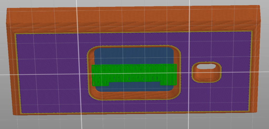
Printing the case flat initially appears to require extensive support for the central hollow on the back, but as is it a flat plane the gap can be bridged with minimal support in the centre. This small piece is easily removable and only adds a minute to the print time.
Conclusion
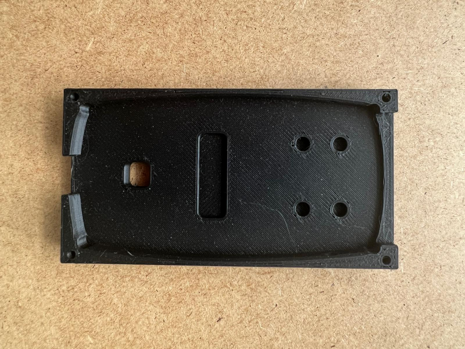
Once the settings were finalised the first prototype was printed ready to be tested on the assembly line.